
Create Mining Block Grids
To access this screen:
-
Reserves ribbon >> Mining Blocks >> Grid.
Mining blocks are the smallest volume the reserves workflow generates. You generate them by splitting up bench solids created earlier in the process.
In addition to splitting bench blocks manually or automatically to achieve a particular mining rate, you can split data using a regular grid with the Create Mining Block Grids task. Grid splitting can be performed in addition to, or instead of, other mine block splitting methods (manually or automatically).
Generated grids are regular. You define a single grid zone and a grid is constructed to split the data on the active bench. You do not need to load any string data because all cutting strings are generated automatically.
Activity steps:
-
Display the Create Mining Block Grids screen.
-
Select the Pit that contains the data you want to split. The model associated with the pit is displayed below.
-
Define the Grid Cutters settings:
-
Anchor Point – Pick your anchor point interactively using the Task window, and/or enter data coordinates. Only X and Y coordinates are required because all segmentation is vertical. Picking honours current snap settings, which is useful if you want to snap to a wireframe vertex or reference data, for example.
-
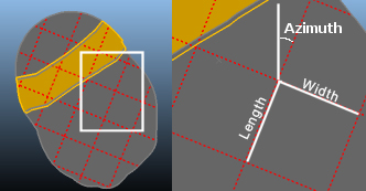
Azimuth – Set the direction of one of the grid axes. This is given as degrees from North in a clockwise direction. You can enter the azimuth directly or select a string segment.
-
Dimensions – Select a length and width for each grid square.
-
-
Select Create Cutters to create grid cutting data using your settings. To view the cutters in the Task window, enable Show Cutters. Then create the blocks.
-
Select how you want to handle minimal volume or thickness blocks, for example ignore the data or merge it:
Merge solids with an area below: merge blocks below the specified area with a neighbour block with which each block shares the largest shared perimeter length. Merging is performed before any subsequent noise removal is applied, using other settings on this panel.
Remove solids with volume below: Any individual block solid that is generated with a volume below the amount specified is automatically removed. This allows insignificant and non-mineable volumes to be ignored.
Remove solids with maximum thickness below: Any individual solid that is generated by the intersection of the Phase DTM with the topography with a thickness below the amount specified is automatically removed. This allows very thin and non-mineable volumes to be ignored.
Note: If selected, merging of blocks with small areas is performed first. Once merging is complete, removal of blocks with a volume or thickness lower than the specified threshold is performed simultaneously afterwards.
-
Click Create Blocks to create the new blocks, removing trivial fragments as specified.
Related topics and activities: